
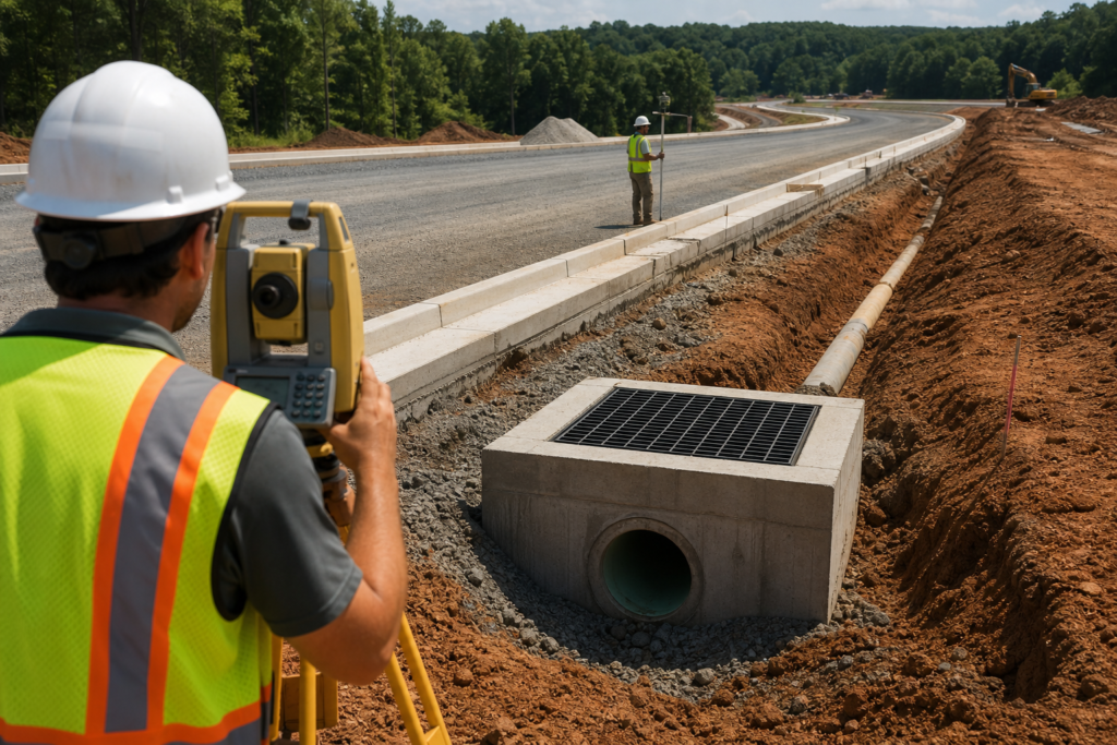
Successful drop inlet hydraulic design is not simply a matter of selecting a standard structure and placing it where water appears. The inlet must match the approved grading and drainage concept, contributing flow, roadway or site conditions, grate configuration, outlet connection, and downstream system.
A standard detail can define construction features, but it does not replace project-specific hydraulic review. This guide explains what developers, engineers, surveyors, contractors, municipalities, and property owners should coordinate before approving plans or beginning construction.
What Drop Inlet Hydraulic Design Must Coordinate
A drop inlet is one component in a connected drainage system. Its location affects where surface water concentrates, while its rim, grate, box, invert, and outlet connection affect how water enters and leaves the structure. Pavement, curb and gutter, swales, slopes, and finished ground must direct water toward the intended capture point without creating an unintended low spot.
The design review should consider the contributing drainage area, expected flow path, proposed surface elevations, roadway geometry, inlet configuration, grate selection, outlet pipe, downstream structures, and discharge conditions. Georgia DOT groups drainage with earthwork, erosion control, pavements, specifications, testing, and inspection in its contractor references, reflecting the coordination required on roadway work. Review Georgia DOT contractor specifications and reference materials for applicable source documents.
Final pipe sizes, inlet spacing, elevations, capacity, and design conditions require project-specific calculations and review by the responsible design professional and approving authority. They should not be inferred from a general service description or selected solely because a standard detail appears similar.
Choose the Inlet Approach Based on Site Conditions

First identify the drainage condition the inlet is intended to serve. This comparison helps organize the design conversation, but it does not prescribe a solution for a particular project.
| Condition | Primary question | Coordination concern |
|---|---|---|
| Low point | Can the inlet safely capture water collecting at the sag? | Confirm ponding behavior, grate capacity, rim elevation, and overflow or bypass conditions. |
| Continuous grade | How much flow reaches the inlet along the roadway or surface slope? | Review flow concentration, grate orientation, longitudinal grade, spacing, and downstream carryover. |
| Curb or roadway | How do curb, gutter, pavement, traffic, and access affect capture and maintenance? | Coordinate the grate, frame, curb line, pavement section, traffic exposure, and construction tolerances. |
| Construction-phase protection | How will sediment be kept out while the site is disturbed? | Use a temporary control suited to the inlet, contributing area, flow pattern, traffic, and maintenance access. |
Georgia DOT’s current standards listing identifies Standard 1019A as a current drop-inlet standard. Its detail notes that it is intended for low points where a lower-capacity grate is sufficient, while a higher-capacity grate may be recommended for an inlet on a continuous grade. That distinction is a design prompt, not a universal selection rule. Review the current Georgia DOT 1019A detail with the approved plans and applicable jurisdictional requirements.
Gather Inputs Before Calculating or Approving the Design
Hydraulic conclusions are only as reliable as the survey, drawings, assumptions, and field information behind them. Assemble:
- Current existing-condition survey, benchmarks, control points, and relevant surface information.
- Approved grading plans showing proposed elevations, contours, slopes, low points, curb lines, pavement, and tie-ins.
- Drainage boundaries and surface-flow directions, including areas added or diverted by the proposed work.
- Roadway geometry, lane or shoulder limits, curb and gutter details, and traffic or maintenance constraints.
- Inlet rim and invert information, grate configuration, structure dimensions, and intended overflow behavior.
- Outlet pipe material, diameter, alignment, slope, connection elevations, and downstream structures or restrictions.
- Applicable erosion-control, stormwater, municipal, owner, and transportation-agency requirements.
- The current plan revision and a process for resolving conflicts between drawings, survey information, and field conditions.
Do not treat a preliminary takeoff, old survey, or conceptual drainage sketch as construction-ready hydraulic information. Identify what is known, what is assumed, and what requires field confirmation. These earthwork grading calculations considerations provide a useful review framework.
Coordinate Rim, Invert, and Surrounding Grades
The rim or grate elevation controls the surface entry point. The invert controls the connection from the structure to the outlet system. Both must relate correctly to pavement, curb, gutter, swales, adjacent grades, and the downstream pipe.
Review elevations in sequence. Confirm current survey control and plan revisions, trace the proposed surface from each contributing area to the inlet, check the grate or rim against the intended low point or grade, verify the inlet invert and pipe slope, and follow the connection to the next structure or discharge point. Compare the design with field conditions before installation.
Design elevations and field verification are related but different deliverables. Clearing, excavation, stockpiling, utility work, or partial grading can alter the surface after the original survey. Document discrepancies and route them to the responsible design or construction decision-maker.
Review Grate Selection, Inlet Capacity, and Flow Concentration
Grate and inlet selection depends on how water approaches the structure. A low point may collect water from multiple directions, while a continuous-grade inlet may receive flow along a curb, gutter, channel, or pavement edge. Concentrated flow, dispersed sheet flow, steep grades, traffic exposure, debris, and maintenance access can all affect performance.
Ask whether the configuration has been evaluated for the expected flow condition, whether ponding is acceptable at the intended location, and whether water can bypass safely if the grate is partially obstructed. Confirm grate alignment with the roadway or surrounding surface and whether the structure can be installed and maintained without creating a traffic or access problem.
A grate described as standard does not necessarily have the capacity required for every location. The responsible design professional should establish the hydraulic criteria and verify the selected arrangement against the approved drainage concept.
Coordinate Pipe Connections and the Downstream System
Follow water from the surface to the inlet, through the structure, along the connecting pipe, through downstream manholes or catch basins, and toward the approved outfall or storage feature. Downstream restrictions can affect the usefulness of an otherwise suitable inlet.
Coordination may involve HDPE, reinforced concrete pipe, ductile iron pipe, roadway crossings, manholes, catch basins, slope drains, flumes, spillways, or an underground pond. Check connection elevations, pipe alignment, bedding and access requirements, utility conflicts, and the sequence in which structures and surrounding grades will be built.
Stormwater design should also be coordinated with erosion control and site stabilization. Georgia’s Environmental Protection Division lists the Georgia Stormwater Management Manual and related stormwater resources among its planning and design references.
Separate Permanent Hydraulic Design from Temporary Inlet Protection
Permanent hydraulic design determines how the completed system collects and conveys water. Temporary inlet protection is a construction-phase sediment-control measure intended to limit sediment entry while soil is disturbed. The two tasks address different risks.
Temporary protection must account for inlet configuration, contributing area, flow concentration, slope, ponding space, traffic, inspection access, and maintenance. It should be coordinated with upstream erosion and sediment controls. Review the distinction between permanent drainage and inlet protection before selecting a construction-phase device.
Protection that obstructs too much flow can create flooding or unsafe ponding, while inadequate protection can allow sediment to enter the structure and downstream system. The erosion-control plan, permit conditions, manufacturer instructions, and responsible inspector should guide installation and maintenance.
Verify Georgia DOT Standards and Other Requirements
For work under Georgia DOT jurisdiction or subject to its requirements, confirm that the design team is using current standards, details, supplements, and approved project documents. Separate details address roadway and median applications. A standard detail should be read with its notes, project plans, drainage calculations, and agency direction.
Identify whether a city, county, owner, utility authority, or other reviewing body has its own construction details or stormwater requirements. The applicable authority may determine which standards govern, what submittals are needed, and who must approve changes. Contractor certification or construction capability does not replace professional design, agency review, or permit obligations.
Plan Construction Verification and Closeout
Before installation, confirm benchmarks, control points, structure locations, rim and invert elevations, pipe connections, and the current drawing revision. During construction, document field conditions and changes rather than relying on informal markups. Verify that the installed structure connects to intended grades and pipes before surrounding work is concealed.
Assign closeout responsibilities at the start. Depending on the project, deliverables may include field records, inspection documentation, revised drawings, survey information, or GDOT as-built GIS submittals. The owner, engineer, surveyor, contractor, and reviewing agency should agree on required formats and responsibility for each item.
Assign Responsibilities Before Requesting a Quote
- Owner or developer: Provide objectives, property information, available plans, schedule, access constraints, and known agency requirements.
- Engineer or design professional: Establish the hydraulic approach, design criteria, calculations, approved elevations, structure selection, and agency submittals.
- Surveyor: Provide current control, existing conditions, layout support, and required field verification.
- Contractor: Price the defined scope, identify assumptions and exclusions, coordinate means and methods, install approved work, and report field conflicts.
- Site team: Coordinate grading, pipes, erosion control, temporary protection, inspections, maintenance, and sequencing.
- Closeout team: Confirm who prepares and submits as-built information.
When requesting a quote, include the latest plans, survey, specifications, inlet schedule, pipe schedule, quantities, access information, construction limits, and desired deliverables. Ask the contractor to separate hydraulic design, layout, estimating, construction, temporary protection, and closeout support.
Where a Civil Site Work Contractor Can Support the Process
A civil site work contractor can support the construction side of drop inlet planning without replacing the responsible engineer or approving authority. DCBC LLC lists drop inlets, catch basins, HDPE, RCP, DIP, manholes, slope drains, roadway crossings, flumes, and spillways among its civil site work capabilities. Its listed support also includes earthwork and grading, erosion control, construction stakeout plans, roadway grade calculations, three-point level verification from survey information, estimation and takeoff, and GDOT as-built GIS submittals.
This combination can help coordinate approved drainage information with grading, pipe installation, erosion control, field layout, construction quantities, and documentation. The exact scope, assumptions, and design responsibility should still be confirmed against project plans.
Frequently Asked Questions
Is a Georgia DOT standard drop inlet detail enough to complete the hydraulic design?
No. A standard detail can provide construction information for an applicable structure, but project-specific review still requires drainage area, flow paths, grades, grate capacity, pipe connections, downstream conditions, and agency requirements.
What is the difference between a low-point inlet and a continuous-grade inlet?
A low-point inlet collects water at a sag or local low area. A continuous-grade inlet receives flow moving along a slope or roadway edge. The approach affects flow concentration, grate capacity, ponding, spacing, and the applicable detail.
Who is responsible for final drop inlet hydraulic design and approval?
Responsibility depends on the delivery method and jurisdiction, but final hydraulic design and approval belong with the designated design professional and reviewing authority. A contractor may support estimating, layout, construction, verification, and documentation without assuming that role.
How do rim and invert elevations affect drop inlet performance?
The rim or grate elevation determines how surface water reaches the inlet, while the invert controls the outlet connection. Both must coordinate with surrounding grades, pipe slope, downstream structures, and the approved drainage concept.
Can temporary inlet protection replace a permanent drop inlet design?
No. Temporary inlet protection manages construction-phase sediment risk. It does not establish the completed system’s location, elevations, capacity, pipe connection, or downstream performance.
What information should I provide when requesting a quote?
Provide the current survey, approved plans, grading and drainage details, inlet and pipe schedules, quantities, construction limits, access restrictions, schedule, erosion-control requirements, and requested layout or closeout deliverables.
Conclusion
Good drop inlet hydraulic design starts with current survey information and approved grading, then follows the actual flow path through the inlet, pipe network, and downstream system. The right approach depends on whether the structure serves a low point, continuous grade, curb, roadway, or construction-phase sediment-control need.
Before construction, confirm responsibility for professional design, agency approval, layout, installation, temporary protection, inspection, maintenance, and as-built documentation. For Georgia civil site work and roadway drainage coordination, DCBC LLC provides listed construction, grading, stormwater, erosion-control, field-verification, estimating, and documentation support that can be scoped to approved project requirements.